Mehta Steels trades and supplies Ms Beams also known as ISMC or Joists :
Mehta Steels is a renowned suppliers of mild steel Beams manufactured by SAIL , Jindal , re rolling mills and other renowned mills around the world.
Mild Steel Beams:
‘Mehta Steels’ commonly supplies ‘I’ & ‘H’ shape light and heavy beams ( ISMB & ISHB) , Joists , Columns, imported profiles , sections like IPN , NPB , WPB , HEA , HEB , UC , UB , etc.
Beams supplied by ‘Mehta Steels’ are available in mild steel grade and high tensile grade
Common dimensions of ms Beams available in ready stock with ‘Mehta Steels’ are:
Common dimensions of ms Beams (ISMB) of Indian origin available in ready stock with ‘Mehta Steels’ are:
| Sr.No. | Deccription | Size | Section weight (KG/Mtrs) |
| 1 | ISMB 125 | 125 X 70 | 13.3 |
| 2 | ISMB 150 | 150 X 75 | 15 |
| 3 | ISMB 200 | 200 X 100 | 24.2 |
| 4 | ISMB 250 | 250 X 125 | 37.3 |
| 5 | ISMB 300 | 300 X 140 | 46 |
| 6 | ISMB 350 | 300 X 140 | 52.4 |
| 7 | ISMB 400 | 400 X 140 | 61.5 |
| 8 | ISMB 450 | 450 X 150 | 72.4 |
| 9 | ISMB 500 | 500 x 180 | 86.9 |
| 10 | ISMB 600 | 600 x 210 | 123 |


Details of imported profile beams supplied by Mehta Steels
Mehta Steels is one of the very few companies in India having expertise in supplying special profile imported sections of beams as per international standards. Mehta Steels Sources this sections from renowned mills around the world and ensures the supply of right quality material , prompt delivery at competitive prices.
Mehta Steels can supply following imported sections:
The commonly used names of international standard steel profiles are
IPE
IPN
HE
HL
HD
HP
ACB - CASTELLATED BEAMS WITH CIRCULAR OPENINGS
CASTELLATED BEAMS WITH HEXAGONAL OPENINGS
ACB – CASTELLATED BEAMS WITH SINUSOIDAL OPENINGS "ANGELINA"
IFB
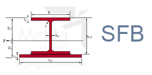
SFB
UB
J
UC
UBP
WIDE FLANGE BEAMS
S
HP
HP
HG
JAPANESE H SECTIONS
Sample DRAWINGS OF SOME OF THE IMPORTED PROFILES OF BEAMS:


PRODUCT RANGE
Universal Beams & Columns, channels and Rails
| Description Beams |
Sectional Weight |
Total Depth |
Flange Width |
Thickness of Web |
Thickness of Flange |
Root radius |
Area of section |
moment of Inertia |
Sectional Modulus |
Radius of gyration |
Remarks | |||
|---|---|---|---|---|---|---|---|---|---|---|---|---|---|---|
| X Axis | Y Axis | X Axis | Y Axis | X Axis | Y Axis | |||||||||
| W | H | B | Tw | Tf | R | A | Ixx | Iyy | Zxx | Zyy | Rxx | Ryy | ||
| Kg/m | mm | mm | mm | mm | mm | cm2 | cm4 | cm4 | cm3 | cm3 | cm | cm | ||
| PARALLEL FLANCE BEAMS; UB SERIES | ||||||||||||||
| UB 203 x 133 x 25 | 25.1 | 203.2 | 133.2 | 5.7 | 7.8 | 7.6 | 31.97 | 2340 | 30.76 | 23.03 | 46.2 | 8.56 | 3.10 | 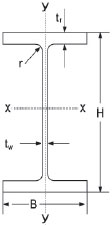 |
| UB 203 x 133 x 30 | 30.0 | 206.8 | 133.9 | 6.4 | 9.6 | 7.6 | 38.21 | 2896 | 384.7 | 280 | 57.5 | 8.71 | 3.17 | |
| UB 254 x 146 x 31 | 31.1 | 251.4 | 146.1 | 6 | 8.6 | 7.6 | 39.68 | 4413 | 447.5 | 351.1 | 61.3 | 10.55 | 3.36 | |
| UB 254 x 146 x 37 | 37.0 | 256 | 146.4 | 6.3 | 10.9 | 7.6 | 47.17 | 5537 | 570.6 | 432.6 | 78 | 10.83 | 3.48 | |
| UB 254 x 146 x 43 | 43.0 | 259.6 | 147.3 | 7.2 | 12.7 | 7.6 | 54.77 | 6544 | 677.4 | 504.1 | 92 | 10.93 | 3.52 | |
| UB 305 x 165 x 40 | 40.3 | 303.4 | 165 | 6 | 10.2 | 8.9 | 51.32 | 8503 | 764.4 | 560.5 | 92.6 | 12.87 | 3.86 | |
| UB 305 x 165 x 46 | 46.1 | 306.6 | 165.7 | 6.7 | 11.8 | 8.9 | 58.75 | 9899 | 895.7 | 645.7 | 108 | 12.98 | 3.90 | |
| UB 305 x 165 x 54 | 54.0 | 310.4 | 166.9 | 7.9 | 13.7 | 8.9 | 68.77 | 11700 | 1063 | 753.6 | 127 | 13.04 | 3.93 | |
| UB 356 x 171 x 45 | 45.0 | 351.4 | 171.1 | 7 | 9.7 | 10.2 | 57.33 | 12070 | 811.1 | 686.7 | 94.81 | 14.51 | 3.76 | |
| UB 356 x 171 x 51 | 51.0 | 355 | 171.5 | 7.4 | 11.5 | 10.2 | 64.91 | 14140 | 968.3 | 769.4 | 112.9 | 14.76 | 3.86 | |
| UB 356 x 171 x 57 | 57.0 | 358 | 172.2 | 8.1 | 13 | 10.2 | 72.56 | 16040 | 1108 | 896 | 128.7 | 14.87 | 3.91 | |
| UB 356 x 171 x 67 | 67.1 | 363.4 | 173.2 | 9.1 | 15.7 | 10.2 | 54.49 | 19460 | 1362 | 1071 | 157.3 | 15.09 | 3.99 | |
| UB 406 x 178 x 54 | 54.1 | 402.6 | 177.7 | 7.7 | 10.9 | 10.2 | 68.95 | 18720 | 1021 | 930 | 115 | 16.48 | 3.85 | |
| UB 406 x 178 x 60 | 60.1 | 406.4 | 177.9 | 7.9 | 12.8 | 10.2 | 76.52 | 21600 | 1203 | 1063 | 135 | 16.8 | 3.97 | |
| UB 406 x 178 x 67 | 67.1 | 409.4 | 198.8 | 8.8 | 14.3 | 10.2 | 85.54 | 24330 | 1365 | 1189 | 153 | 16.87 | 3.99 | |
| UB 406 x 178 x 74 | 74.2 | 412.8 | 179.5 | 9.5 | 16 | 10.2 | 94.51 | 27310 | 1545 | 1323 | 172 | 17 | 4.04 | |
| UB 457 x 152 x 52 | 52.3 | 449.8 | 152.4 | 7.6 | 10.9 | 10.2 | 66.64 | 21370 | 645 | 950 | 84.64 | 17.91 | 3.11 | |
| UB 457 x 152 x 60 | 59.8 | 454.6 | 152.9 | 8.1 | 13.3 | 10. 2 | 76.23 | 25500 | 794.6 | 1122 | 103.9 | 18.29 | 3.23 | |
| UB 457 x 152 x 67 | 67.2 | 458 | 153.8 | 9 | 15 | 10.2 | 85.55 | 28930 | 912.6 | 1263 | 118.7 | 18.39 | 3.27 | |
| UB 457 x 152 x 74 | 74.2 | 462 | 154.4 | 9.6 | 17 | 10.2 | 94.48 | 32670 | 1047 | 1414 | 135.6 | 18.6 | 3.33 | |
| UB 457 x 152 x 82 | 82.1 | 465.8 | 155.3 | 10.5 | 18.9 | 10.2 | 104.5 | 36590 | 1185 | 1571 | 152.5 | 18.71 | 3.37 | |
| UB 457 x 191 x 67 | 67.1 | 453.4 | 189.9 | 8.5 | 12.7 | 10.2 | 85.51 | 29380 | 1452 | 1296 | 152.9 | 18.54 | 4.12 | |
| UB 457 x 191 x 74 | 74.3 | 457 | 190.4 | 9 | 14.5 | 10.2 | 94.63 | 33320 | 1671 | 1458 | 175.5 | 18.76 | 4.20 | |
| UB 457 x 191 x 82 | 82.0 | 460 | 191.3 | 9.9 | 16 | 10.2 | 104.5 | 37050 | 1871 | 1611 | 195.6 | 18.83 | 4.23 | |
| UB 457 x 191 x 89 | 89.3 | 463.4 | 191.9 | 10.5 | 17.7 | 10.2 | 113.8 | 41020 | 2089 | 1770 | 217.8 | 18.99 | 4.29 | |
| UB 457 x 191 x 98 | 98.3 | 467.2 | 192.8 | 11.4 | 19.6 | 10.2 | 125.3 | 45730 | 2347 | 1957 | 243.5 | 19.11 | 4.33 | |
| Description Beams |
Sectional Weight |
Total Depth |
Flange Width |
Thickness of Web |
Thickness of Flange |
Root radius |
Area of section |
moment of Inertia |
Sectional Modulus |
Radius of gyration |
Remarks | |||
|---|---|---|---|---|---|---|---|---|---|---|---|---|---|---|
| X Axis | Y Axis | X Axis | Y Axis | X Axis | Y Axis | |||||||||
| W | H | B | Tw | Tf | R | A | Ixx | Iyy | Zxx | Zyy | Rxx | Ryy | ||
| Kg/m | mm | mm | mm | mm | mm | cm2 | cm4 | cm4 | cm3 | cm3 | cm | cm | ||
| PARALLEL FLANGE BEAMS; UB SERIES CONTD.... | ||||||||||||||
| UB 533 x 210 x 82 | 82.2 | 528.8 | 208.8 | 9.6 | 13.2 | 12.7 | 104.7 | 47540 | 2007 | 1800 | 192.3 | 21.31 | 4.38 | |
| UB 533 x 210 x 92 | 92.1 | 533.1 | 209.3 | 10.1 | 15.6 | 12.7 | 117.4 | 55230 | 2389 | 2072 | 228.3 | 21.69 | 4.51 | |
| UB 533 x 210 x 101 | 101.0 | 536.7 | 210 | 10.8 | 17.4 | 12.7 | 128.7 | 61520 | 2692 | 2292 | 256.4 | 21.87 | 4.57 | |
| UB 533 x 210 x 109 | 109.0 | 539.5 | 210.8 | 11.6 | 18.8 | 12.7 | 138.9 | 66820 | 2943 | 2477 | 279.2 | 21.94 | 4.60 | |
| UB 533 x 210 x 122 | 122.0 | 544.5 | 211.9 | 12.7 | 21.3 | 12.7 | 155.4 | 76040 | 3388 | 2793 | 319.7 | 22.12 | 4.67 | |
| UB 610 x 229 x 101 | 101.2 | 602.6 | 227.6 | 10.5 | 14.8 | 12.7 | 128.9 | 75780 | 2915 | 2545 | 256 | 24.24 | 4.75 | |
| UB 610 x 229 x 113 | 113.0 | 607.6 | 228.2 | 11.1 | 17.3 | 12.7 | 143.9 | 87320 | 3434 | 2874 | 301 | 24.63 | 4.88 | |
| UB 610 x 229 x 125.1 | 125.1 | 612.2 | 229 | 11.9 | 19.6 | 12.7 | 159.3 | 98610 | 3932 | 3221 | 343 | 24.88 | 4.97 | |
| UB 610 x 229 x 139.9 | 139.9 | 617.2 | 230.2 | 13.1 | 22.1 | 12.7 | 178.2 | 111800 | 4505 | 3622 | 391 | 25.05 | 5.03 | |
| PARALLEL FLANGE BEAMS; NPB/IPE SERIES | ||||||||||||||
| IPE 100/NPB 100X55 | 8.1 | 100 | 55 | 4.1 | 5.7 | 7 | 10.3 | 171 | 15.9 | 34.2 | 5.8 | 4.07 | 1.24 | |
| IPE 100/NPB 120X60 | 10.37 | 120 | 64 | 4.4 | 6.3 | 7 | 13.2 | 318 | 27.7 | 53 | 8.6 | 4.9 | 1.45 | |
| IPE 100/NPB 140X70 | 12.89 | 140 | 73 | 4.7 | 6.9 | 7 | 16.4 | 541 | 44.9 | 77.3 | 12.3 | 5.74 | 1.65 | |
| IPE 100/NPB 160X80 | 15.77 | 160 | 82 | 5 | 7.4 | 9 | 20.1 | 869 | 68.3 | 108.7 | 16.7 | 6.58 | 1.84 | |
| IPEA 180/NPB 180X90 | 15.37 | 177 | 91 | 4.3 | 6.5 | 9 | 19.6 | 1063 | 81.9 | 120.1 | 18 | 7.37 | 2.05 | |
| IPE 180/NPB 180X90 | 18.8 | 180 | 91 | 5.3 | 8 | 9 | 23.9 | 1317 | 100.9 | 146.3 | 22.2 | 7.42 | 2.05 | |
| IPEO 180/NPB 200X100 | 25.09 | 202 | 102 | 6.2 | 9.5 | 12 | 32 | 2211 | 168.9 | 218.9 | 331 | 8.32 | 2.3 | |
| NPB 200X130 | 27.37 | 207 | 133 | 5.8 | 8.5 | 12 | 34.9 | 2666 | 334 | 257.5 | 50.2 | 8.74 | 3.1 | |
| NPB 200X130 | 31.55 | 210 | 134 | 6.4 | 10 | 12 | 40.2 | 3153 | 401.9 | 300.3 | 60 | 8.86 | 3.16 | |
| IPEA 220/NPB 220X110 | 22.18 | 217 | 110 | 5 | 7.7 | 12 | 28.3 | 2317 | 171.4 | 213.5 | 31.2 | 9.05 | 2.46 | |
| IPE 220/NPB 220X110 | 26.2 | 220 | 120 | 6.2 | 9.8 | 15 | 39.1 | 3892 | 283.6 | 324.3 | 47.3 | 9.97 | 2.69 | |
| IPEO 240/NPB 240X120 | 34.31 | 242 | 122 | 7 | 10.8 | 15 | 43.7 | 4369 | 328.5 | 361.1 | 53.9 | 10 | 2.74 | |
| IPEA 270/NPB 270X135 | 30.73 | 267 | 135 | 5.5 | 8.7 | 15 | 39.1 | 4917 | 358 | 368.3 | 53 | 11.21 | 3.02 | |
| IPE270/NPB 270X135 | 36.07 | 270 | 135 | 6.6 | 10.2 | 15 | 45.9 | 5790 | 419.9 | 428.9 | 62.2 | 11.23 | 3.02 | |
| IPEO 270/NPB 270X135 | 42.26 | 274 | 136 | 7.5 | 12.1 | 15 | 53.8 | 6947 | 513.5 | 507.1 | 75.5 | 11.36 | 3.09 | |
| IPEA 300/NPB 300x150x36.5 | 36.5 | 297 | 150 | 6.1 | 9.2 | 15 | 46.53 | 7173 | 519 | 483.1 | 69.2 | 12.42 | 3.34 | |
| IPE 300/NPB 300X150X42.2 | 42.2 | 300 | 150 | 7.1 | 10.7 | 15 | 53.81 | 8356 | 603.8 | 557.1 | 80.5 | 12.46 | 3.35 | |
| IPEO 300/NPB 300X 150X49.3 | 49.3 | 304 | 152 | 8 | 12.7 | 15 | 62.83 | 9994 | 745.7 | 657.5 | 98.12 | 12.61 | 3.45 | |
| Description Beams |
Sectional Weight |
Total Depth |
Flange Width |
Thickness of Web |
Thickness of Flange |
Root radius |
Area of section |
moment of Inertia |
Sectional Modulus |
Radius of gyration |
Remarks | |||
|---|---|---|---|---|---|---|---|---|---|---|---|---|---|---|
| X Axis | Y Axis | X Axis | Y Axis | X Axis | Y Axis | |||||||||
| W | H | B | Tw | Tf | R | A | Ixx | Iyy | Zxx | Zyy | Rxx | Ryy | ||
| Kg/m | mm | mm | mm | mm | mm | cm2 | cm4 | cm4 | cm3 | cm3 | cm | cm | ||
| PARALLEL PLANGE BEAMS; NPB/IPE SERIES CONTD... | ||||||||||||||
| IPE A360/NPB350X170X50.2 | 50.2 | 357.6 | 170.0 | 6.6 | 11.5 | 18.0 | 64.0 | 14520 | 944.3 | 811.8 | 111.1 | 15.06 | 3.84 | |
| IPE 360/NPB 350X170X57.1 | 57.1 | 360.0 | 170.0 | 8.0 | 12.7 | 18.0 | 72.7 | 16270 | 1043 | 903.6 | 122.8 | 14.95 | 3.79 | |
| IPEO 360/NPB 350X170X 66 | 66.0 | 364.0 | 172.0 | 9.2 | 14.7 | 18.0 | 84.0 | 19050 | 1251 | 1047 | 145.5 | 15.05 | 3.86 | |
| IPEA 400/ NPB 400X180X57.4 | 57.4 | 397 | 180 | 7 | 12 | 21 | 73.1 | 20293 | 1170.6 | 1022.3 | 130.1 | 16.66 | 4.00 | |
| IPE 400/NPB 400X180X66.3 | 66.3 | 400 | 180 | 8.6 | 13.5 | 21 | 84.5 | 23128 | 1317.8 | 1156.4 | 146.4 | 16.55 | 3.95 | |
| IPEO 400/NPB 400X180X75.7 | 75.7 | 404 | 182 | 9.7 | 15.5 | 21 | 96.5 | 26747 | 1564.2 | 1324.1 | 171.9 | 16.66 | 4.03 | |
| IPEA 450/NPB 450X190X67.2 | 67.2 | 447 | 190 | 7.6 | 13.1 | 21 | 85.5 | 29759 | 1502.4 | 1331.5 | 158.1 | 18.65 | 4.19 | |
| IPE 450/NPB 450X190X77.6 | 77.6 | 450 | 190 | 9.4 | 14.6 | 21 | 98.8 | 33743 | 1675.9 | 1499.7 | 176.4 | 18.48 | 4.12 | |
| IPEO 450/NPB 450X 190X92.4 | 92.4 | 456 | 192 | 11 | 17.6 | 21 | 117.7 | 40923 | 2085.4 | 1798.9 | 217.2 | 18.65 | 4.21 | |
| IPEA 500/NPB 500X200X79.4 | 79.4 | 497 | 200 | 8.4 | 14.5 | 21 | 101.3 | 42933 | 1939.32 | 1727.7 | 193.9 | 2061 | 4.38 | |
| IPE 500/NPB 500X200X90.7 | 90.7 | 500 | 200 | 10.2 | 16 | 21 | 115.5 | 48199 | 2141.7 | 1927.9 | 241.2 | 20.43 | 4.31 | |
| IPEO 500/NPB 500X200X107 | 107.0 | 506 | 202 | 12 | 19 | 21 | 136.7 | 57777 | 2621.7 | 2283.7 | 259.6 | 20.56 | 4.38 | |
| IPEA 600/NPB 600X220X108.0 | 108.0 | 597 | 220 | 9.8 | 17.5 | 24 | 137 | 82919 | 3116.6 | 2777.8 | 283.3 | 24.6 | 4.77 | |
| IPE 600/NPB 600X220X122.0 | 122.0 | 600 | 220 | 12 | 19 | 24 | 156 | 92083 | 3387.3 | 3069.3 | 307.9 | 24.3 | 4.66 | |
| IPEO 600/NPB 600X220X154.0 | 154.0 | 610 | 224 | 15 | 24 | 24 | 196.8 | 118302 | 4520.8 | 3678.8 | 403.6 | 24.52 | 4.79 | PARALLEL FLANGE BEAMS; WPB/HE SERIES |
| HEAA 320/WPB 320X300X74.2 | 74.2 | 301 | 300 | 8.0 | 11 | 27 | 94.58 | 16450 | 4959 | 4093 | 330.6 | 13.19 | 7.24 | |
| HEA 320/WPB 320X300X97.6 | 97.6 | 310 | 300 | 9.0 | 15.5 | 27 | 124.4 | 22930 | 6985 | 1479 | 465.7 | 13.58 | 7.49 | |
| HEB 320/WPB 320X300X127 | 127.0 | 320 | 300 | 11.5 | 20.5 | 27 | 161.3 | 30820 | 9239 | 1929 | 615.9 | 1382 | 7.57 | |
| HEM 320/WPB 320X300X245 | 245.0 | 359 | 309 | 21 | 40 | 27 | 312 | 68130 | 19710 | 3796 | 1276 | 14.78 | 7.95 | |
| HEAA 600/WPB 600X300X129 | 129.0 | 571 | 300 | 12 | 15.5 | 27 | 164.1 | 91872 | 6993.4 | 3217.9 | 466.2 | 23.66 | 6.53 | |
| HEA 600/WPB 600X300X178 | 178.0 | 590 | 300 | 13 | 25 | 27 | 226.5 | 141208 | 11271.3 | 4786.7 | 751.4 | 24.97 | 7.05 | |
| HEB 600/WPB 700X300X212 | 212.0 | 600 | 300 | 15.5 | 30 | 27 | 270 | 171041 | 13530.2 | 5701.4 | 902 | 25.17 | 7.08 | |
| HEM 600/WPB 600X300X285 | 285.0 | 620 | 305 | 21 | 40 | 27 | 363.7 | 237447 | 18975.5 | 7659.6 | 1244.3 | 25.65 | 7.22 | |
| HEAA 700/WPB 700X300X150 | 150.0 | 670 | 300 | 13 | 17 | 27 | 190.9 | 142721 | 7673.1 | 4260.3 | 511.5 | 27.34 | 6.34 | |
| HEA 700/WPB 700X300X204 | 204.0 | 690 | 300 | 14.5 | 27 | 27 | 260.5 | 215301 | 12178.8 | 6240.6 | 811.9 | 28.75 | 6.65 | |
| HEB 700/WPB 700X300X241 | 241.0 | 700 | 300 | 17 | 32 | 27 | 306.4 | 256888 | 14440.8 | 7339.7 | 952.7 | 28.96 | 6.68 | |
| HEM 700/WPB 700X300X301 | 301.0 | 716 | 304 | 21 | 40 | 27 | 383 | 329278 | 18797.4 | 9197.7 | 1236.7 | 29.32 | 7.01 | |
| HEAA 800/WPB 800X300X172 | 172.0 | 770 | 300 | 14 | 18 | 30 | 218.5 | 208882 | 8133.7 | 5425.5 | 542.2 | 30.92 | 6.10 | |
| HEA 800/WPB800X300X224 | 224.0 | 790 | 300 | 15 | 28 | 30 | 285.8 | 303442 | 12638.7 | 7682.1 | 842.6 | 32.58 | 6.65 | |
| HEB WPB 800X300X262 | 262.0 | 800 | 300 | 17.5 | 33 | 30 | 334.2 | 359083 | 14903.7 | 8977.1 | 993.6 | 32.78 | 6.68 | |
| HEM 800/WPB 800X300X317 | 317.0 | 814 | 303 | 21 | 40 | 30 | 404.3 | 442598 | 18627.4 | 10875 | 1229.5 | 33.09 | 6.79 | |
| HE 800X373 | 373.0 | 826 | 308 | 25 | 46 | 30 | 474.6 | 523900 | 22530 | 12690 | 1463 | 33.23 | 6.89 | |
| HEA 900/WPB 900X300X252 | 252.0 | 890 | 300 | 16 | 30 | 30 | 320.5 | 422075 | 13547.5 | 9484.8 | 903.2 | 36.29 | 6.50 | |
| HEB 900/WPB 900X300X291 | 291.0 | 900 | 300 | 18.5 | 32 | 30 | 371.3 | 494065 | 15815.9 | 10979 | 1054.4 | 36.48 | 6.53 | |
| HEM 900/WPB 900X300X333 | 333.0 | 910 | 302 | 27 | 40 | 30 | 432.6 | 570400 | 18450 | 12540 | 1222 | 36.7 | 6.60 | |
| Description Beams |
Sectional Weight |
Total Depth |
Flange Width |
Thickness of Web |
Thickness of Flange |
Root radius |
Area of section |
moment of Inertia |
Sectional Modulus |
Radius of gyration |
Remarks | |||
|---|---|---|---|---|---|---|---|---|---|---|---|---|---|---|
| X Axis | Y Axis | X Axis | Y Axis | X Axis | Y Axis | |||||||||
| W | H | B | Tw | Tf | R | A | Ixx | Iyy | Zxx | Zyy | Rxx | Ryy | ||
| Kg/m | mm | mm | mm | mm | mm | cm2 | cm4 | cm4 | cm3 | cm3 | cm | cm | ||
| PARALLEL FLANGE COLUMS; UC SERIES | ||||||||||||||
| UC 152X152X23 | 23.0 | 152.4 | 153.2 | 5.8 | 6.8 | 7.6 | 29.25 | 1250 | 399.9 | 164 | 52.55 | 6.54 | 3.70 | Equivalent to WPB 150x150x23 |
| UC 152X152X30 | 30.0 | 157.6 | 152.9 | 6.5 | 9.4 | 7.6 | 38.26 | 1748 | 560.5 | 221.8 | 73.31 | 6.76 | 3.83 | Equivalent to WPB 150x150x30 |
| UC 152X152X37 | 37.0 | 161.8 | 154.4 | 8 | 11.5 | 7.6 | 47.11 | 2210 | 706.2 | 273.2 | 9148 | 6.85 | 3.87 | Equivalent to WPB 150x150x37 |
| UC 203X203X46 | 46.1 | 23.2 | 203.6 | 7.2 | 11 | 10.2 | 58.73 | 4568 | 1548 | 449.6 | 152.1 | 8.82 | 5.13 | 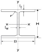 |
| UC 203 X203X52 | 52.0 | 206.2 | 204.3 | 7.9 | 12.5 | 10.2 | 66.28 | 5259 | 1778 | 510.1 | 174 | 8.91 | 5.18 | |
| UC 203 X203X60 | 60.0 | 209.6 | 205.8 | 9.4 | 14.2 | 10.2 | 76.27 | 6125 | 2065 | 584.4 | 200.6 | 8.96 | 5.20 | |
| UC 203 X203X71 | 71.0 | 215.8 | 206.4 | 10 | 17.3 | 10.2 | 90.43 | 7618 | 2537 | 706 | 245.9 | 9.18 | 5.30 | |
| UC 203 X203X86 | 86.1 | 222.2 | 209.1 | 12.7 | 20.5 | 10.2 | 109.6 | 9449 | 3127 | 850.5 | 299.1 | 9.28 | 5.34 | |
| UC 254X254X73 | 73.1 | 254.1 | 254.6 | 8.6 | 14.2 | 12.7 | 93.1 | 11420 | 3908 | 894.9 | 307 | 110.7 | 6.48 | |
| UC 254X254X89 | 88.9 | 260.3 | 256.3 | 10.3 | 17.3 | 12.7 | 113.3 | 14270 | 4857 | 1096 | 379 | 11.22 | 6.55 | |
| UC 254X254X107 | 107.1 | 266.7 | 258.8 | 12.8 | 20.5 | 12.7 | 136.4 | 17510 | 5928 | 1313 | 458.1 | 11.33 | 6.59 | |
| UC 254X254X132 | 132.0 | 276.3 | 261.3 | 15.3 | 25.3 | 12.7 | 138.1 | 22530 | 7531 | 1631 | 576.4 | 11.58 | 6.69 | |
| UC 254X254X167 | 167.1 | 289.1 | 265.2 | 19.2 | 31.7 | 12.7 | 212.9 | 30000 | 9870 | 2075 | 744.3 | 11.87 | 6.81 | |
| UC 305X305X97 | 96.9 | 307.9 | 305.3 | 9.9 | 15.4 | 15.2 | 123.4 | 22250 | 7308 | 1445 | 478.7 | 13.42 | 7.69 | |
| UC 305X305X118 | 117.9 | 314.5 | 307.4 | 12 | 18.7 | 15.2 | 150.2 | 27670 | 9059 | 1760 | 589.4 | 13.57 | 7.77 | |
| UC 305X305X137 | 136.9 | 320.5 | 309.2 | 13.8 | 21.7 | 15.2 | 174.4 | 32810 | 10700 | 2048 | 692.2 | 1372 | 7.83 | |
| UC 305X305X158 | 158.1 | 327.1 | 311.2 | 15.8 | 25 | 15.2 | 203.4 | 38750 | 12570 | 2369 | 807.8 | 13.87 | 7.90 | |
| UC 305X305X198 | 198.1 | 339.9 | 314.5 | 19.1 | 31.4 | 15.2 | 252.4 | 50900 | 16300 | 2995 | 1037 | 14.2 | 8.04 | |
| UC 305X305X240 | 240.0 | 352.5 | 318.4 | 23 | 37.7 | 15.2 | 305.8 | 64200 | 20310 | 3643 | 1276 | 14.49 | 8.15 | |
| UC 305X305X283 | 282.9 | 365.3 | 322.2 | 26.8 | 44.1 | 15.2 | 360.4 | 78870 | 24630 | 4318 | 1529 | 14.79 | 8.27 | |
| UC 356X368X129 | 129.0 | 355.6 | 368.6 | 10.4 | 17.5 | 15.2 | 164.3 | 40250 | 14610 | 2264 | 792.8 | 15.65 | 9.43 | |
| UC 356X368X153 | 152.9 | 362 | 370.5 | 12.3 | 20.7 | 15.2 | 194.8 | 48590 | 17550 | 2684 | 947.5 | 15.79 | 9.49 | |
| UC 356X368X177 | 177.0 | 368.2 | 372.6 | 14.4 | 23.8 | 15.2 | 225.5 | 57120 | 20530 | 310.3 | 11.2 | 15.91 | 9.54 | |
| UC 356X368X202 | 201.9 | 374.6 | 374.7 | 16.5 | 27 | 15.2 | 257.2 | 66260 | 23690 | 3538 | 1264 | 16.05 | 9.60 | |
| Description Beams |
Sectional Weight |
Total Depth |
Flange Width |
Thickness of Web |
Thickness of Flange |
Flange Slope, Max |
Distance of Centre of Gravity |
Area of section |
moment of Inertia |
Sectional Modulus |
Radius of gyration |
Remarks | ||||||
|---|---|---|---|---|---|---|---|---|---|---|---|---|---|---|---|---|---|---|
| Y Axis | X Axis | Y Axis | X Axis | Y Axis | ||||||||||||||
| W | H | B | Tw | Tf | R | Cyy | Ixx | Iyy | Zxx | Zyy | Rxx | Ryy | ||||||
| Kg/m | mm | mm | mm | mm | deg. | cm2 | cm4 | cm4 | cm3 | cm3 | cm | cm | ||||||
| INDIAN CHANNELS | ||||||||||||||||||
| MC 75 | 7.14 | 75 | 40 | 4.8 | 7.5 | 96 | 1.32 | 9.1 | 78.5 | 12.9 | 20.9 | 4.81 | 2.94 | 1.19 |  |
|||
| MC 100 | 9.56 | 100 | 50 | 5.0 | 7.7 | 96 | 1.54 | 12.2 | 192 | 26.7 | 33.5 | 7.71 | 3.97 | 1.48 | ||||
| MC 125 | 13.1 | 125 | 65 | 5.3 | 8.2 | 96 | 1.95 | 16.7 | 425 | 61.1 | 68.1 | 13.4 | 5.05 | 1.91 | ||||
| MC 150 | 16.8 | 150 | 75 | 5.7 | 9.0 | 96 | 2.20 | 21.3 | 788 | 103 | 105 | 19.5 | 6.08 | 2.20 | ||||
| MC 175 | 19.6 | 175 | 75 | 6.0 | 10.2 | 96 | 2.19 | 24.9 | 1240 | 122 | 141 | 23.0 | 7.04 | 2.21 | ||||
| MC 200 | 22.3 | 200 | 75 | 6.2 | 11.4 | 96 | 2.20 | 28.5 | 1830 | 141 | 181 | 26.4 | 8.02 | 2.22 | ||||
| MC 250 | 30.6 | 250 | 80 | 7.2 | 14.1 | 96 | 2.30 | 39.0 | 3880 | 211 | 307 | 38.5 | 9.92 | 2.37 | ||||
| ISMC 250 | 34.2 | 250 | 82 | 9 | 14.1 | 2.23 | 43.5 | 4080 | 244 | 326 | 40.9 | 9.68 | 2.37 | |||||
| MC 300 | 36.3 | 300 | 90 | 7.8 | 13.6 | 96 | 2.35 | 46.3 | 6420 | 313 | 428 | 47.1 | 11.80 | 2.60 | ||||
| ISMC 400 | 50.1 | 400 | 100 | 8.8 | 15.3 | 2.42 | 63.8 | 15200 | 5.8 | 760 | 67 | 15.4 | 2.82 | |||||
| Description | Sectional Weight |
Thickness | Root radius | Distance of Centre of Gravity |
Area of section |
Moment of Inertia | Sectional Modulus | Radius of gyration | Remarks | |||||||||
| X Axis | Y Axis | U Axis | V Axis | X Axis | Y Axis | X Axis | Y Axis | U Axis | V Axis | 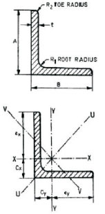 |
||||||||
| w | t | R1 | R2 | Cx | Cy | A | lxx | lyy | luu | lvv | Zxx | Zyy | rxx | ryy | luu | lvv | ||
| Kg/m | mm | mm | mm | mm | cm | cm2 | cm4 | cm4 | cm4 | cm4 | cm3 | cm3 | cm | cm | cm4 | cm4 | ||
| EQUAL LEG ANGLES | ||||||||||||||||||
| 100 100X8 | 12.1 | 8.0 | 8.5 | Should be reasonbly square |
2.76 | 2.76 | 15.4 | 145 | 145 | 232 | 58.4 | 20.0 | 20.0 | 3.07 | 3.07 | 3.88 | 1.95 | |
| X10 | 14.9 | 10.0 | 2.84 | 2.84 | 19.0 | 177 | 177 | 282 | 71.8 | 24.7 | 24.7 | 3.05 | 3.05 | 3.85 | 1.94 | |||
| X12 | 17.7 | 12.0 | 2.92 | 2.92 | 22.6 | 207 | 207 | 329 | 84.7 | 29.2 | 29.2 | 3.03 | 3.03 | 3.82 | 1.94 | |||
| 110 110X8 | 13.4 | 8.0 | 10.0 | 4.8 | 3.00 | 3.00 | 17.1 | 197 | 197 | 313 | 81.0 | 24.6 | 24.6 | 3.40 | 3.40 | 4.28 | 2.18 | |
| X10 | 16.6 | 10.0 | 3.09 | 3.09 | 3.09 | 21.1 | 240 | 240 | 381 | 98.9 | 30.4 | 3.37 | 3.37 | 4.25 | 2.16 | |||
| X12 | 19.7 | 12.0 | 3.17 | 3.17 | 25.1 | 281 | 281 | 446 | 116 | 35.9 | 35.9 | 3.35 | 3.35 | 4.22 | 2.15 | |||
| 130 130 X10 | 19.7 | 10.0 | 10.0 | 4.8 | 3.59 | 3.59 | 25.1 | 405 | 405 | 640 | 166 | 43.1 | 43.1 | 4.02 | 4.02 | 5.07 | 2.57 | |
| X12 | 23.5 | 12.0 | 3.67 | 3.67 | 29.9 | 476 | 476 | 757 | 169 | 51.0 | 51.0 | 3.99 | 3.99 | 5.03 | 2.56 | |||
| 150 150X10 | 22.9 | 10.0 | 12 | 4.8 | 4.08 | 4.08 | 29.2 | 634 | 634 | 1010 | 260 | 58.0 | 58.0 | 4.66 | 4.66 | 5.87 | 2.98 | |
| X12 | 27.3 | 12.0 | 4.16 | 4.16 | 34.8 | 746 | 746 | 1190 | 306 | 68.8 | 68.8 | 4.63 | 4.63 | 5.84 | 2.97 | |||
| X16 | 35.8 | 16.0 | 4.31 | 4.31 | 45.6 | 959 | 959 | 1520 | 395 | 89.7 | 89.7 | 4.58 | 4.58 | 5.77 | 2.94 | |||
| 200 200X16 | 48.5 | 16.0 | 15 | 4.8 | 5.56 | 5.56 | 61.8 | 2370 | 2370 | 3760 | 968 | 164 | 164 | 6.19 | 6.19 | 7.80 | 3.96 | |
| X20 | 60.0 | 20.0 | 5.71 | 5.71 | 76.4 | 2880 | 2880 | 4570 | 1180 | 201 | 201 | 6.14 | 6.14 | 7.73 | 3.93 | |||
| INDIAN CRAINE RAILS | Sectional Weight (Kg/m) | ||
| CR-80 | 64.2 | As per is :3443-1980 (INDIAN SPECIFICATION FOR CRANE RAIL SECTIONS) | 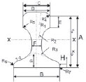 |
| CR-100 | 89.0 |
| TRACK RAILS | Sectional Weight (Kg/m) | ||
| UIC 54 | 54.43 | As per IRS-T-12 2009, UIC-860-R, or EN-13671-1 | |
| UIC 60 | 60.34 | ||
| IRS 52 | 51.89 | As per IRS-T-12-2009 |
Delivery Conditions for Beams / Columns /Channels and Rails
| For Structurals | For Rails | ||
| Lenght: | For prime | 10 - 13 meter (-0/+100mm) | 13meter, lenght, tolerance as per norm |
| For non-prime | 10-13 meter(-0/+100mm) | ||
| For short lenght | As per lot information | ||
| Dimensional Norms: (for prime & short-lenght material only) |
For UB/UC sections | As per BS4-1 :1993 | As per UIC/ EN/ IRS norm as applicable |
| For IPE/NPB sections | As IS :12778/ equivalance with EN-19-57 | ||
| For HE/WPB sections | As per IS:12778/ equivalance with EN-53-62 | ||
| Surface Condition: | For prime | Blue or with slight atmospheric rust | |
| For non-prime/short lenght | superflcial rust to slight rusted material to be acceptable | ||
| Packing : | Bare, Loose and / or in bundles of max 5 MT each | Bare, Loose and / or in bundles of max 5 MT each | |
| Marking: | For prime | Size lenght/ Grade /Heat no, Order no, Desired shipping marks | As per mutual agreement |
| For non-prime /short lenght | As per mutual greement | ||
| Minimum Order Qty. : | For domestic sales : 5 MT per size per lenght and 22 MT IN total .(In case of lesser order quantitiy, freight for full trailor / truck to buyer’s account) | As per mutual agreement | |
| For exprots : 30 MT per lenght and 100 MT per grade for grades S355JR/ equivalent and lower; Total order quantity MIN 500 MT 50 MT per size per lenght and 100 MT per grade for grades S355JR/equivalent and heigher; Total order quantity : Min 500 MT |
|||
| Invoicing : | For domestic sales : On actual weight basis of as per mutual agrement | For domestic sales : On actual weight basis | |
| For expots : On theoretical weight basis on nominal size & lengh | For exports : On theoretica weight basis | ||
Kindly mail us all your enquiries and queries related to Imported sections , Special Profiles and Jindal make beams to ankit.mehta@mehtasteels.com
